Studio ENG 4 Fall 2012
Computer Lab
All of the students will have access to the computer lab in 1116 Academic Surge. Log in to the computers with your Kerberos ID and passphrase. The lab is typically open from 8 AM to 8 PM M-Th and 8 AM to 6 PM on Fridays, but is often booked for other classes. Academic Surge 1044 also has 24 computers with the same software and more open lab time. See the Fall 2012 schedule for details or check out the schedule posted at the doors.
Software
Inkscape
Inkscape is an open source and free vector graphics editor available for most operating systems. It is very suitable for professional engineering diagrams. It is based around the Scalable Vector Graphics (*.svg) format but can also read and write to other vector formats. It can also export drawings to bitmap/raster images. With practice highly realistic 2D images can be created. We will learn the basics of Inkscape and create some engineering diagrams.
Tutorials
The Inkscape documentation website has lots of general tutorials. We will follow this basic tutorial for a free body diagram in the studio session.
AutoDesk Inventor
You will use AutoDesk Inventor 2013 for the majority of your studio work. Inventor is a modern mechanical 3D parametric solid modeling software pacakge. It offers basic solid model creation tools, automatic 2D print generation, and many other modules for various types of engineering analysis. Proficiency in Inventor is highly in-demand skill and will provide the background needed to pick up many other similar software packages.
Autodesk provides a student and educator oriented resource web site at http://students.autodesk.com. Free academic versions of Inventor can be downloaded there with a valid university email address. Check the system requirements and make sure your computer meets them before downloading and installing[1]. Make sure to download the 2013 version so that the files are compatible with the 2013 version installed in the computer lab.
Tutorials
You will be using the official Autodesk Inventor Tutorials during the studio session and also during homework. They can be viewed at the Autodesk Help Wiki among other things.
Pack and Go
Inventor uses projects (*.ipj file) to provide a map to the many files it generates. You will need to make use of the Pack and Go feature to collect all files from a project. Follow these instructions to pack and go your projects for submission.
Project
You will be assigned to a group of 3 or 4 in studio and will be tasked with modeling a relatively complex mechanical assembly of your own choosing. The project will be part reverse engineering and part design. You will collectively select a product/machine/object that you think needs a design improvement. Maybe you never want to open the lid of your trash can again and would like to come up with an automatic opener or your desk needs adjustable legs for standing and sitting. The design change to improve the object should be some simple addition, we are not asking you redesign the whole thing. You will ultimately model something that already exists but with something additional to improve it just a little. Ideally, all of you should have access to this thing so that you can see it, touch it, and measure it. The majority of your work will be reverse engineering but some element of the assembly must be a new design.
You will be required to submit a professional quality project report detailing the modeling project and a team member evaluation.
The project should be handed in as a complete report with the drawings and printout as an appendix in PDF format. Grades for the project will be done on a group basis so be sure to proof each other's work.
Projects are due during the last studio period, 1 hour before the end of the studio. Submit your reports directly to your TA. The final hour of the last studio will be an informal presentation to show and describe your group's model to the class. Have your model or images of your model on a USB stick so that you can load them onto the main computer. Each teammate should describe portions of the model that they worked on and what they learned while doing it. This is an informal presentation, slides are not needed and everything should be casual, just like a show and tell in elementary school.
Contact your TA in case they have additional requirements.
Requirements
Everything below should be submitted in a single zip file.
Project report
This report should be of professional quality and submitted as a single PDF file with all graphics embedded and all working drawings included. The lab computers have Abode Acrobat which will allow you to assemble any individual PDF files together into one document.
Title page with project name, team member names, studio section day, TA name, and date.
A table of contents
Project summary
- Describe the assembly that was modeled including the design improvement.
- Describe the individual parts that were modeled.
- Describe who modeled which parts, the assemblies, and the working drawings.
- Describe how the team accomplished the project, how well you worked together, and what the teamwork taught you.
A description of the modeling process, e.g. state the basic steps used to create the model.
Difficulties you ran into (e.g. things you couldn't model, parts that took a long time, communication issues, team work load, etc.) and your solutions.
Improvements to the model you would like to make and additional challenges you would like to explore given more time.
Solid model of the entire assembly
This should include a collection of Inventor part and assembly files that make up the entire object. Be sure to use Inventor's Pack and Go option. Make it clear which assembly file is the main file with a clear name, e.g. Desk-Main.iam.
Assembly drawing of entire model assembly
- This should be a working drawing with an exploded view. Make use of the presentation files to create this.
- Include a parts list and label all parts.
- Label drawing with all group member names.
One working drawing for each modeled part
- Label drawings with group member who created the model.
- Label each part with a descriptive name and number it according to the assembly drawing parts list.
- Include the most important dimensions for the reverse engineered portion and all of the dimensions for the added feature.
A printout of the solid model from within Inventor
- Save a aesthetically appealing image of your model. You can use the different view options to add shading, shadows, and different perspectives.
- Use transparency or multiple views where appropriate to show maximum detail. This may also be used on your title page!
Tentative Grading
Summary: 10 pts
Modeling Process Description: 5 pts
Format & Other: 5 pts
Modeling:
- Parts: 30 pts
- Detail Drawings: 15 pts
- Assembly: 15 pts
Individual Effort and Instructor Judgment: 20 pts
Sample Projects
The following images show some final screenshots of previous years' projects. Keep in mind that these were strictly reverse engineering projects and had no design component.
| Ceiling Fan | 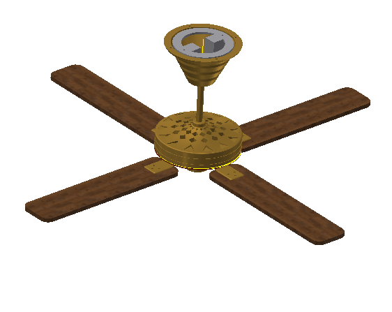 |
| Skateboard | 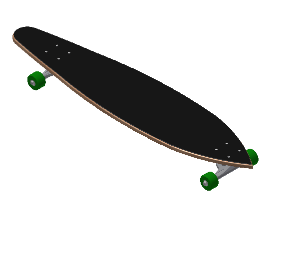 |
| Guitar | 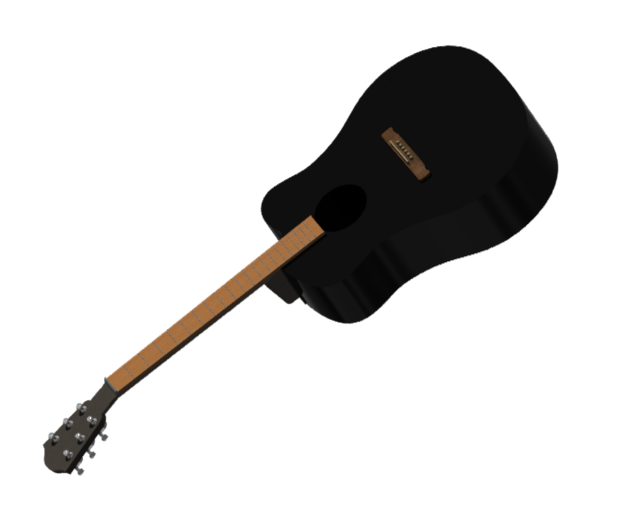 |
| Lock | 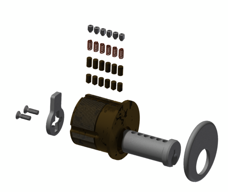 |
Footnotes
| [1] | Inventor is only available for Windows, but Macintosh and Linux users may be able to run Inventor with a virtual machine or dual booting. See this Mac FAQ for suggestions. Unfortunately, either solution requires you to have a valid copy of Windows. |